
Actuators in Automation and Control Systems: Integration and Control Strategies
Actuators
Definition
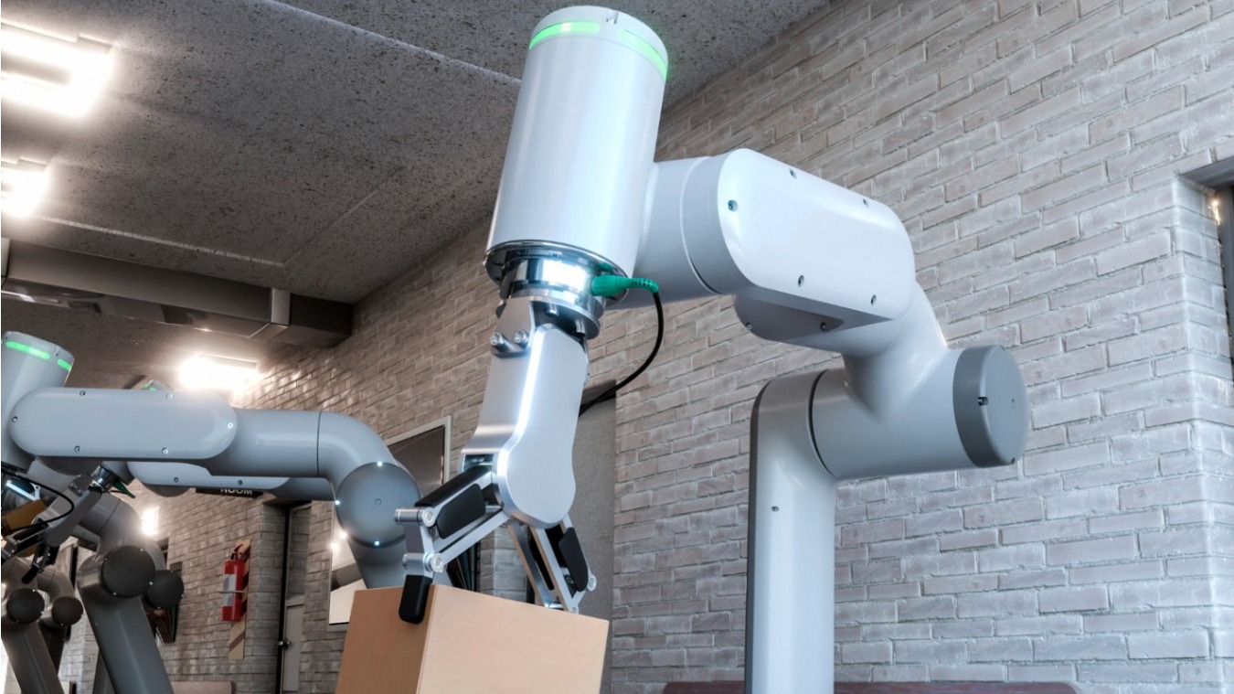
Actuators are devices that convert energy (electric, hydraulic, or pneumatic) into controlled motion or force. They produce linear or rotary movement in response to a control signal to move or control mechanisms such as valves, robotic arms, or machinery. Actuators enable automated systems to perform physical tasks reliably and accurately.
Overview
Actuators in Automation and Control Systems: Integration and Control Strategies
In automated systems, actuators convert control signals into mechanical output and therefore define the achievable performance of the control loop. Effective integration of actuators into control systems combines selection of the appropriate actuator type with the right control architecture, feedback sensors, communication protocols, and safety measures. This entry focuses on control strategies, feedback integration, real-time considerations, and practical integration patterns for industrial automation.
Control objectives and actuation modes
Actuators are commanded to meet specific control objectives: position, velocity, force/torque, or a hybrid of these (impedance control).
Typical actuation modes include:
- Position control: The actuator must achieve and maintain a specified angular or linear position with defined accuracy and repeatability. Common in robotics, pick-and-place, and valve positioning.
- Velocity control: The actuator regulates speed rather than absolute position. Found in conveyor drives and spindle drives.
- Force or torque control: The actuator maintains a force or torque setpoint, used in compliant assembly, torque-limited toolheads, and haptic interfaces.
- Impedance/admittance control: Combines position and force control to manage interaction dynamics with the environment—important in collaborative robots and contact-rich tasks.
Feedback sensors and signal conditioning
Closed-loop operation requires sensors that measure the actuator state. Common sensors include incremental and absolute encoders for rotary position, linear encoders and LVDTs for linear position, tachometers for velocity, and load cells or strain gauges for force sensing. High-performance systems use high-resolution encoders and low-latency signal conditioning to improve stability and bandwidth. Sensor selection must consider resolution, accuracy, hysteresis, environmental protection, and sampling rate.
Control algorithms and implementation
Control systems implement algorithms that translate desired trajectories into actuator commands. Standard techniques include PID control for single-loop position/velocity control, feedforward compensation for predictable dynamics, and model-based control (state-space, observers, adaptive control) for higher performance in the presence of plant nonlinearities. Motion controllers support trajectory planning, ramp shaping, and jerk-limited profiles to meet mechanical constraints and reduce wear.
Drive electronics and motion controllers
Electric actuators require drives or amplifiers that manage current, voltage, and commutation. Servo drives accept high-level motion commands and implement current/velocity/position loops internally. Stepper motors are controlled by microstepping drivers that convert step/dir pulses into precise micro-steps. Pneumatic and hydraulic actuators are often driven via directional and proportional valves; proportional valves provide continuous control of flow and pressure for smoother motion.
Communication and integration protocols
Deterministic and low-latency communication is essential for multi-axis coordinated motion. Common industrial networks include EtherCAT, CANopen, ProfiNet IRT, and real-time Ethernet variants. Fieldbuses and industrial Ethernet protocols determine update rates, synchronization capabilities, and ease of integration with PLCs, motion controllers, and PLC-RTOS platforms. Selection affects achievable control bandwidth and synchronized multi-axis trajectories.
Real-time performance and latency
Actuator control is sensitive to loop timing. Sampling rates, communication cycle time, and computational latency influence stability and disturbance rejection. High-bandwidth systems use embedded servo loops with millisecond or sub-millisecond update rates; centralized controllers must ensure bounded latency to prevent performance degradation. Time synchronization mechanisms (PTP, distributed clocks) maintain coherent multi-axis motion and accurate timestamping for diagnostics.
Safety, diagnostics, and fault handling
Actuator integration must incorporate safety measures such as limiting devices, emergency-stop logic, safe torque off (STO) for drives, mechanical stops, and monitoring for overcurrent, overtemperature, and encoder faults. Diagnostics include current and position monitoring, drift detection, and predictive maintenance metrics (vibration, temperature trends). Fault-handling strategies should define graceful degradation modes, redundancy for critical functions, and clear failure states to minimize downtime and risk.
Practical integration patterns and examples
- Coordinated multi-axis systems (robotic arms, gantry systems) use a master motion controller to send synchronized setpoints to distributed servo drives over EtherCAT, ensuring timing coherence for smooth trajectories.
- Conveyor and sorter systems use velocity-controlled motors with encoders and digital I/O for zone control; photoelectric sensors provide feedback for object detection and indexing.
- Valve actuation in process automation integrates position feedback and a positioner loop, where the actuator receives a 4-20 mA signal and the controller adjusts valve position to meet flow or pressure setpoints.
Best practices for actuator control integration
- Match sensor resolution and bandwidth to the control loop requirements; over-resolution with insufficient bandwidth yields no practical benefit.
- Use closed-loop control whenever load variations or precision requirements demand it; reserve open-loop designs for simple, repeatable tasks with margin.
- Plan wiring, grounding, and shielding to reduce EMI and protect encoder signals; separate power and signal cables where practical.
- Implement staged safety and fault-handling with clear priorities: immediate shutdown for hazardous faults, controlled stop for recoverable events, and predictive alerts for maintenance scheduling.
By understanding the interaction between actuator physics, sensors, control algorithms, and communications, engineers can design automation systems that meet required performance, robustness, and safety targets. Proper integration minimizes unexpected behavior, reduces maintenance, and increases system uptime.
Sources And Additional Reading (3)
- Electric Actuator Technology Comparison
“Electric Actuator Technology Comparison.” Tolomatic, https://www.tolomatic.com/info-center/resource-details/electric-actuator-technology-comparison-integrated-and-traditional-designs/.
- Valve Basics: Electric Actuator Controls
“Valve Basics: Electric Actuator Controls.” Valve Magazine, https://valvemagazine.com/articles/valve-basics-electric-actuator-controls/.
- Electric Linear Actuators & Controllers
“Electric Linear Actuators & Controllers.” IAI America, https://www.intelligentactuator.com/.
More from this term
Looking for a 3PL?
Compare warehouses on Racklify and find the right logistics partner for your business.