
Photo-Eye (PE) Failure Modes, Troubleshooting, and Maintenance Best Practices

Photo-Eye (PE)
Definition
A Photo-Eye (PE) is an optical sensor mounted along a conveyor that detects the presence or absence of a package by sensing a light beam. Acting like the system’s traffic lights, they trigger controls such as stop, start, divert, or counting to manage flow and prevent collisions.
Overview
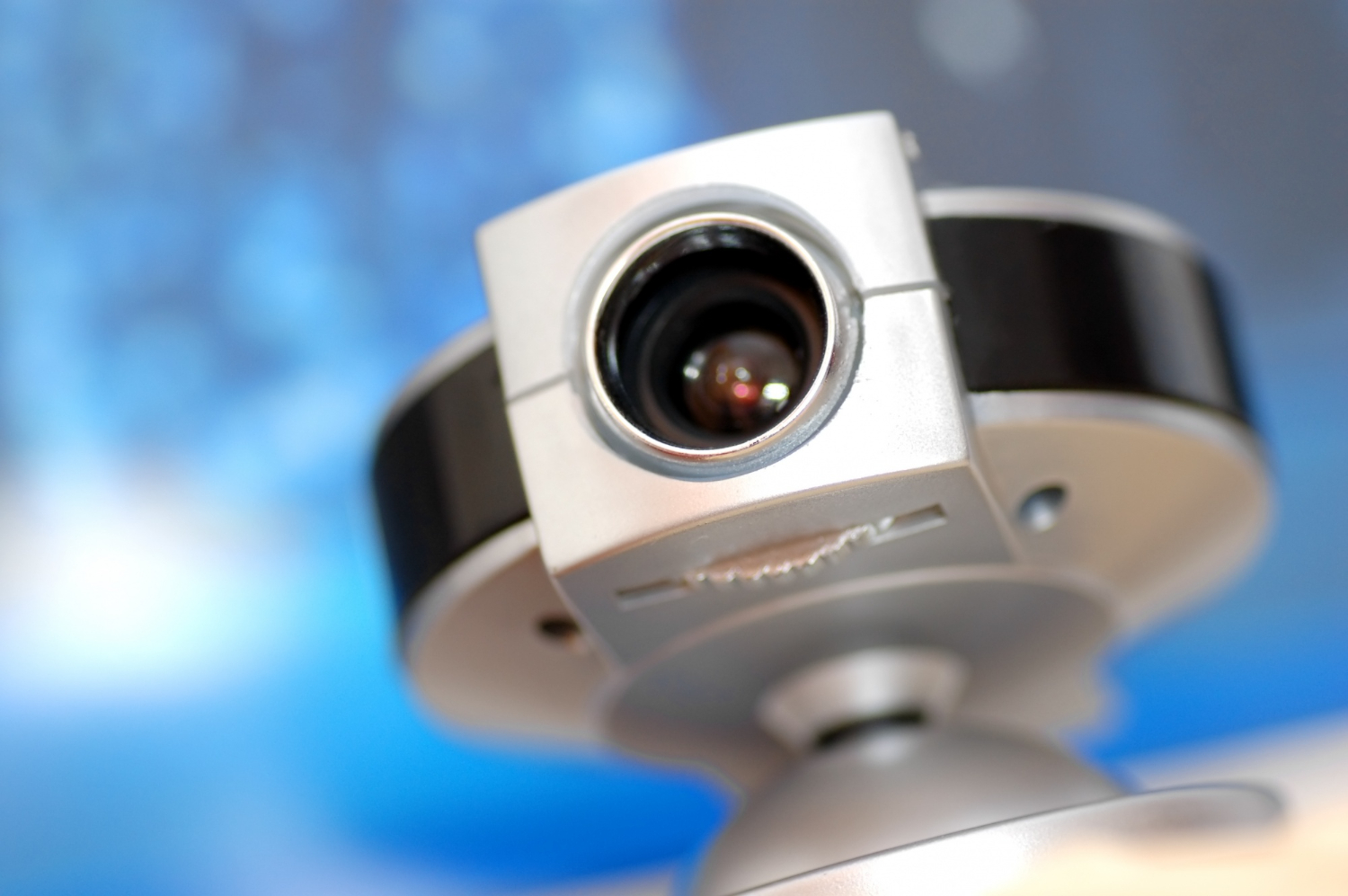
Photo-Eye (PE) Failure Modes, Troubleshooting, and Maintenance Best Practices
Photo-Eye (PE) sensors are robust but can experience failures or degraded performance due to environmental, mechanical, optical, or electrical causes. Understanding common failure modes and applying systematic troubleshooting methods minimizes downtime and avoids repeated failures.
Common failure modes and root causes:
- Contamination of optics: Dust, oil, condensation, or packaging residue on emitter/receiver windows reduces transmitted or received light, lowering signal amplitude and causing intermittent or permanent missed detections.
- Misalignment: Vibration, impact, or thermal expansion can shift emitter/receiver geometry or reflector position, particularly in through-beam and retroreflective setups.
- Ambient light interference: Direct sunlight or strong artificial lighting can saturate the receiver if the sensor lacks adequate modulation or filtering.
- Electrical faults: Wiring breaks, loose connectors, reversed polarity, short circuits, or incorrect output type selection (PNP vs. NPN) cause no output or incorrect logic states. EMI from motors, VFDs, or heavy cable runs can induce spurious signals.
- Component aging: LED emitter intensity degrades over time; photodetectors and electronic components may drift, affecting sensitivity and repeatability.
- Physical damage: Impact, abrasion, or ingress of moisture can mechanically damage housings or internal circuitry.
Structured troubleshooting procedure:
- Verify symptoms: Collect precise failure descriptions (miss counts, intermittent triggers, constant activation) and correlate with time, speed, environmental events, and PLC logs.
- Visual inspection: Check optics for contamination, scratches, or condensation. Inspect mounts and reflectors for physical displacement. Confirm connectors are secure and correct cable types are used.
- Check indicators: Use onboard signal-strength LEDs or diagnostics if available. A low signal indicator often points to contamination or misalignment; a steady but incorrect output may indicate target characteristics or logic inversion.
- Test alignment and optical path: For through-beam and retroreflective systems, temporarily block the beam to confirm expected output transitions. Use alignment tools or a target card to verify centering. For diffuse sensors, present a known good target (white card) to validate switching.
- Electrical verification: With power off, verify wiring continuity and connector pinouts. With power on, measure supply voltage stability and output voltages with a multimeter or scope. Confirm that the controller input type matches the sensor output (PNP sourcing vs. NPN sinking).
- Test with replacement: Substitute a known-good PE or swap with an identical sensor to isolate the failure to the device or the system. If a replacement solves the issue, compare serial diagnostics to identify degradation patterns.
- Monitor under load: Use an oscilloscope or data logger to view raw signal timing and amplitude during normal operation, especially for intermittent failures at high conveyor speeds.
Maintenance and preventive measures:
- Scheduled cleaning: Implement a cleaning regimen based on environment—daily in dusty or greasy locations, weekly in cleaner areas. Use appropriate solvents and lint-free cloths to avoid lens damage.
- Protective hardware: Add shrouds, windows, or air-purge fittings to keep optics clear. Install wire guards or housings where impact or splash is possible.
- Mounting robustness: Use vibration-isolating mounts or rigid brackets with locknuts and thread locker. Include alignment marks so reinstallation returns sensors to nominal geometry.
- Electrical protection: Fit surge suppressors, RC filters, or ferrite beads to mitigate EMI. Ensure correct cable routing separated from high-voltage power runs.
- Diagnostics and logging: Employ sensors with RSSI outputs or IO-Link reporting. Monitor signal trends to predict failures due to gradual contamination or LED aging.
- Spare parts strategy: Stock calibrated replacement PEs and mounting hardware. Keep standardized connector types to reduce interchange errors in field replacement.
Common implementation mistakes to avoid:
- Using diffuse PEs for long-range detection where through-beam is required, resulting in unreliable detection.
- Failing to account for target reflectivity and color during selection, leading to missed detections for dark or transparent objects.
- Neglecting to provide mechanical protection or robust mounting in high-vibration or impact-prone areas.
- Assuming that a PE can serve as a safety device without proper certification and redundant architecture.
By applying a proactive maintenance program, selecting appropriate sensor types, and following systematic troubleshooting procedures, Photo-Eye (PE) sensors can deliver long-term, reliable performance in industrial environments. Proper documentation, spare strategies, and modern diagnostics reduce mean time to repair and help maintain continuous material flow in automated operations.
More from this term
Looking for a 3PL?
Compare warehouses on Racklify and find the right logistics partner for your business.